PKS604P View Datasheet(PDF) - Power Integrations, Inc
Part Name
Description
MFG CO.
PKS604P
PeakSwitch Family Enhanced, Energy-Efficient, Off-Line Switcher IC With Super Peak Power Performance
Power Integrations, Inc

'PKS604P' PDF : 24 Pages View PDF
PKS603-607
Parameter
Conditions
Symbol
SOURCE = 0 V; TJ = -40 to 125 °C
See Figure 18
Min
Typ
(Unless Otherwise Specified)
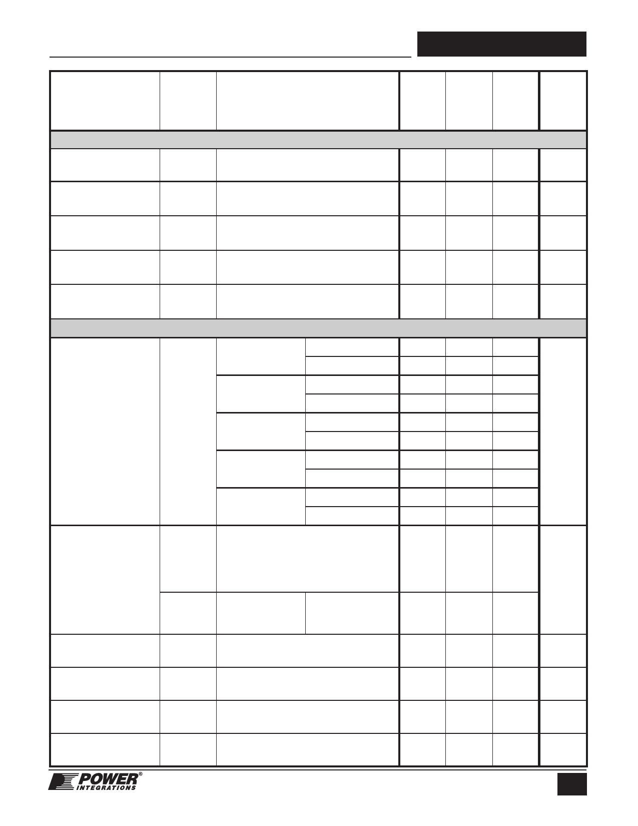
CIRCUIT PROTECTION (cont.)
Initial Current Limit IINIT
Leading Edge
Blanking Time
tLEB
See Figure 21
See Note F
TJ = 25 °C
See Note F
0.75 ×
ILIMIT(Min)
170
215
Current Limit
Delay
tILD
TJ = 25 °C
See Notes F, G
150
Thermal Shutdown
Temperature
135
142
Thermal Shutdown
Hysteresis
75
OUTPUT
PKS603
TJ = 25 °C
7.8
ID = 81 mA
TJ = 100 °C
11.7
PKS604
TJ = 25 °C
5.2
ID = 150 mA
TJ = 100 °C
7.8
ON-State
Resistance
RDS(ON)
PKS605
ID = 200 mA
TJ = 25 °C
TJ = 100 °C
3.9
5.8
PKS606
TJ = 25 °C
2.6
ID = 300 mA
TJ = 100 °C
3.9
PKS607
TJ = 25 °C
2.0
ID = 300 mA
TJ = 100 °C
3.0
IDSS1
OFF-State Drain
Leakage Current
VBP = 6.2 V
VEN/UV = 0 V
VDS = 560 V
TJ = 125 °C
See Note H
IDSS2
VBP = 6.2 V
VEN/UV = 0 V
VDS = 375 V
TJ = 50 °C
See Note H
15
Breakdown
Voltage
BVDSS
VBP = 6.2 V, VEN/UV = 0 V,
See Note I, TJ = 25 °C
700
Drain Supply
Voltage
50
Output EN/UV
Delay
tEN/UV
See Figure 20
Output Disable
Setup Time
tDST
0.5
Max Units
mA
ns
ns
150
°C
°C
9.0
13.5
6.0
9.0
4.5
W
6.7
3.0
4.5
2.3
3.5
200
mA
V
V
5
ms
ms
15
Rev. I 02/07
Share Link: 